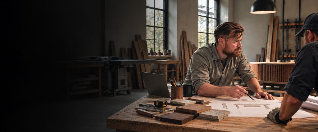
Project · Fitted kitchen · 2025
Fitted kitchen under a sloped ceiling: 21 modules, almost no repetition
A sloped ceiling removes the one thing that makes kitchen documentation straightforward — repetition. Here is how the pack was built so the workshop could cut one-off parts with confidence.

The brief
A joinery workshop had an approved kitchen design and a signed-off layout. What they did not have was production documentation — the set of drawings, cutting lists and material data their own shop floor would build from. They sent me the design intent and the site survey, and I produced the pack.
The kitchen runs along a wall under a pitched roof. Twenty-one modules in total, split across six numbering runs — the 100 series for the tall units, the 200s for base units, the 300s for the upper run, then 400, 500 and 600 series for the island, appliance housings and finishing elements. Two decor materials throughout: U727 ST9 and K532 AD.
The constraint: the ceiling angle
Kitchen documentation is normally efficient because kitchens repeat. You draw one 600 mm wall unit properly and then multiply it. The cutting list has quantities of four and six and twelve against each part, and the shop batches them.
A sloped ceiling destroys that. Every upper module sits at a different height, every top edge is cut to a different angle, and the cornice geometry changes continuously along the run. The quantity column in the cutting list reads 1, 1, 1, 1 all the way down. There is no batching and no second chance — each panel is effectively bespoke.
Documented by hand, this is exactly where errors get made and panels get cut twice. Every dimension is a separate manual calculation, and a single transcription slip becomes a scrapped sheet of 18 mm board.
How it was solved
The whole run was modelled parametrically in Autodesk Inventor with Woodwork for Inventor, and the ceiling was modelled as an actual geometric plane rather than a set of numbers. That makes the roof pitch a single driven constraint. Each upper module references the plane, trims itself to it, and reports its own height.
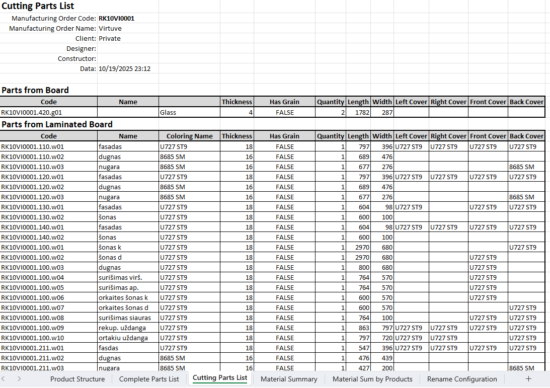
The practical consequence: when the survey came back with a slightly different pitch than the drawing assumed, one constraint changed and all twenty-one modules re-resolved. Nothing was redrawn. The cutting list and the material summary regenerate from the model, so they cannot drift out of step with the geometry the way a spreadsheet maintained by hand always eventually does.
That is the real deliverable here. Not eighteen sheets of paper — a cutting list the shop could trust for parts that were nearly all one-offs.
Two materials, two machining sets
Because the kitchen used two decors, the routed components were issued as two separate drawing sets — one for the U727 ST9 parts and one for the K532 AD parts. This is a small thing that saves real time at the machine. The operator setting up a run in one material gets only the parts in that material, with no filtering and no risk of pulling the wrong panel from the adjacent stack.
The pack also went through revision during production. Two panels in the 100 series needed their routing updated after a hardware decision changed, and that was issued as a marked revision rather than a quietly replaced file — so the shop could see what had changed and check whether anything was already cut. A separate five-sheet set recorded the fronts once the client had approved the decor layout.
What the client received
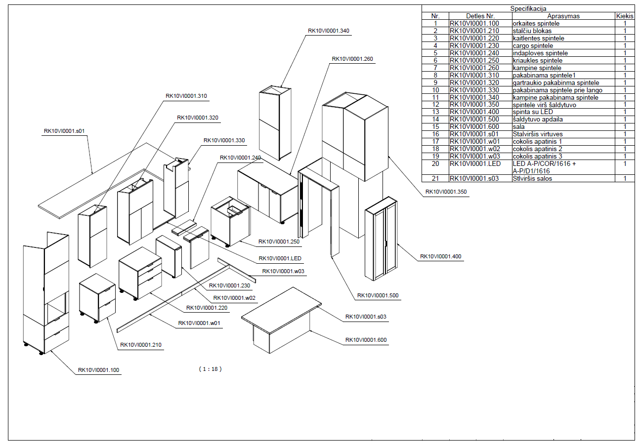
- Exploded assembly view of the complete run, with module numbering
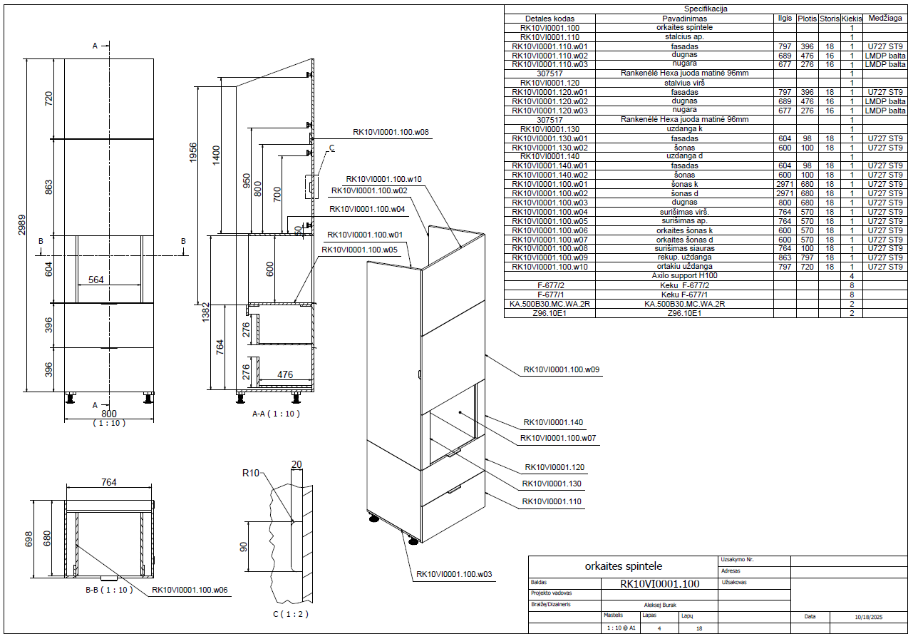
- Module-level production drawings across 18 A1 sheets — the core pack
- Routing and machining drawings issued separately per decor — 3 sheets for U727 ST9, 4 sheets for K532 AD
- A 5-sheet fronts approval set for client sign-off before cutting
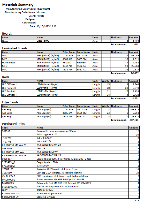
- Cutting list as editable XLSX — part code, dimensions, quantity, material
- Material summary for procurement, grouped by decor
- A marked revision sheet issued mid-production, not a silent file swap
Thirty-one A1 sheets in total. The 18-sheet core pack is what the shop floor builds from; the remaining thirteen are the machining sets, the approval set and the revision — the parts of a documentation package that people forget to count until they need them.
Why module level was the right depth
This pack documents each module as an assembly — the panels shown together, dimensioned, with drilling positions and hardware called out — rather than giving every individual panel its own sheet. For a workshop with experienced cabinetmakers and a beam saw driven from the cutting list, that is the efficient depth. Eighteen sheets instead of sixty, and nothing the shop needs is missing.
Where a job needs every panel drawn individually, I go to part level instead. The vanity unit project shows what that looks like — four modules, forty sheets. Choosing the right depth for the job is most of what keeps documentation affordable.
See this pack for yourself
The core module-level pack from this kitchen is available to download — 18 sheets plus the cutting list and material summary, watermarked but fully legible. No form to fill in.
Other projects
Client name, address and order number are withheld. Every drawing shown is published with permission.