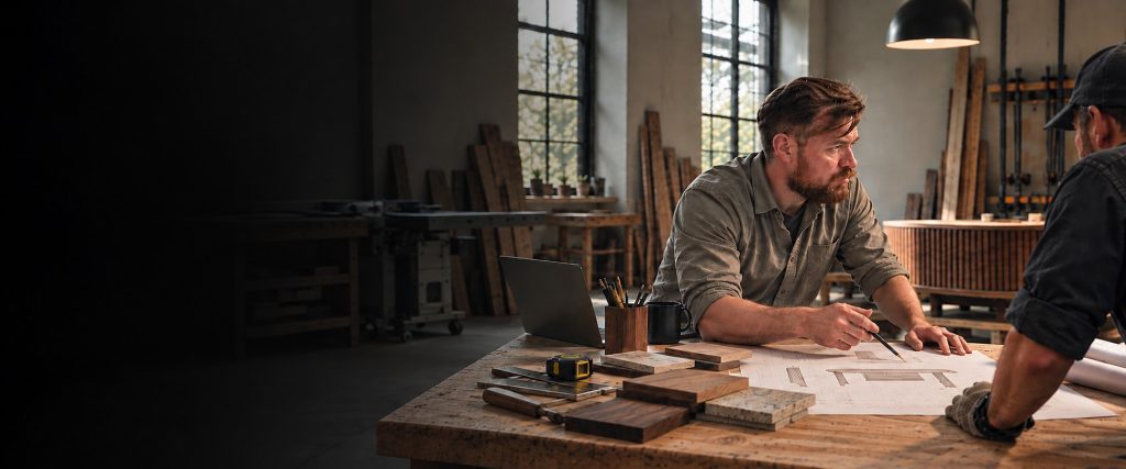
Project · Retail joinery · 2024
A children’s climbing unit that three different trades had to build from
Welded steel frame, sheet metal components, joinery carcassing. Seventy-five sheets for twenty modules — and the sheet count is the story.

The brief
A bookshop wanted a climbing and reading unit for children — part play structure, part shelving, permanently installed in a retail space. Children climb on it, so it carries load and it has to be safe. It also has to look like furniture, not like scaffolding with books on it.
That combination is why it ended up as the largest and most demanding pack of the four projects on this site, and the clearest demonstration of what I mean by multi-material engineering. Twenty modules in the VG00WD3880 series, built around a welded steel frame in 40 × 40 × 2 mm box section, with sheet metal components and conventional panel carcassing fixed to it.
The constraint: one drawing set, three workshops
Most furniture documentation is read by one kind of person. This pack had to be read by three, and each of them works in a different set of conventions:
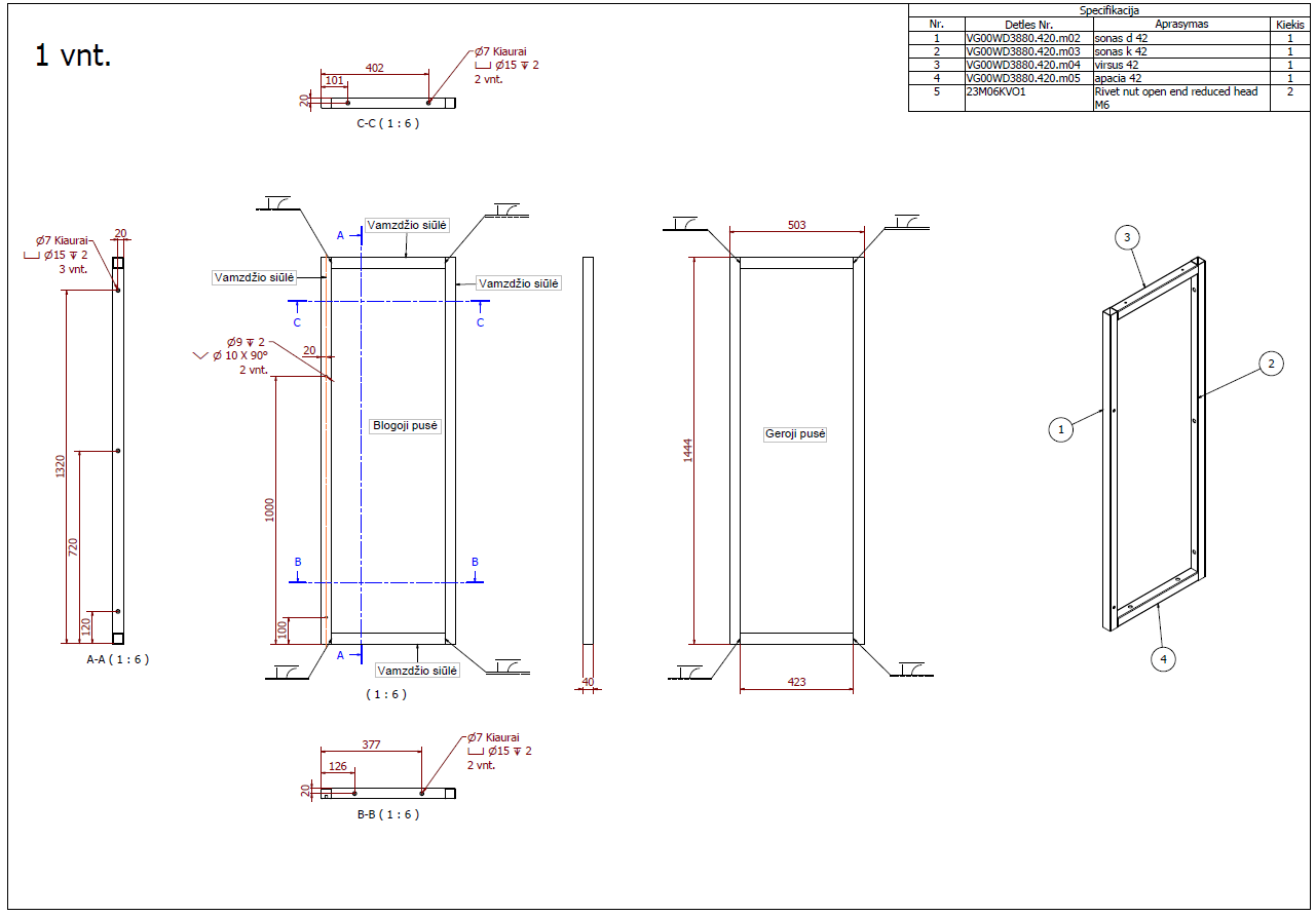
The welder needs tube lengths, mitre and end-cut angles, weld positions and weld types, and a sequence that keeps the frame square while it is being assembled. A welder does not want a cutting list; they want a frame drawing they can set out on a bench.
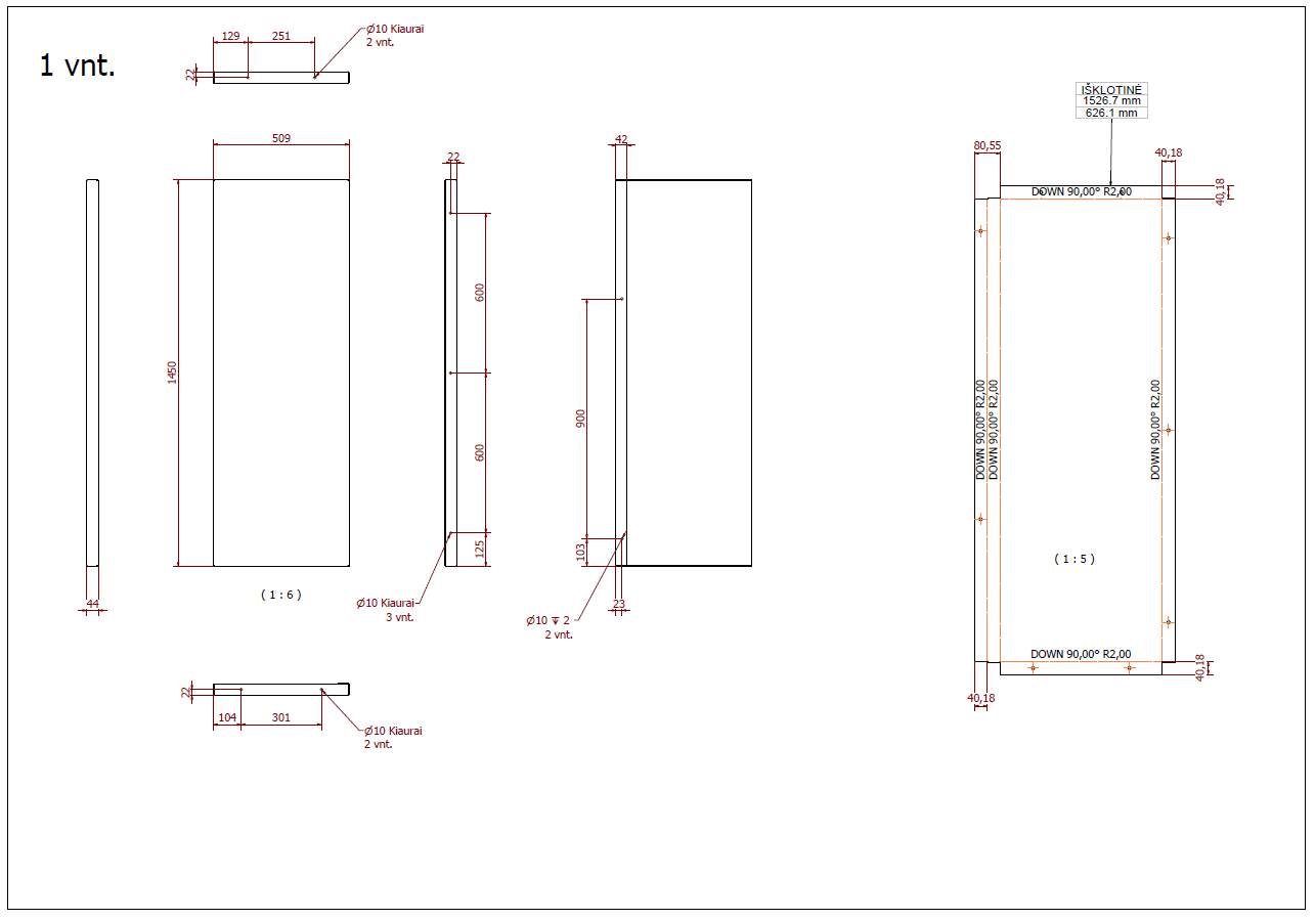
The sheet metal shop needs something quite different: flat patterns with bend lines, bend directions and angles, and allowances that match the press brake actually being used. A folded part is drawn twice — once as it ends up, once as it starts.
The joinery floor needs what joinery always needs — panel sizes, drilling positions, edge treatment, a cutting list.
The hard part is not producing three sets of drawings. It is making sure the interfaces between them meet. A joinery panel that fixes to a welded frame has to account for the weld bead, and for the fact that a fabricated steel frame is not as dimensionally predictable as a machined panel.
How it was solved
Everything — steel, sheet metal and panel — was modelled in one assembly rather than as three separate jobs coordinated by eye. Autodesk Inventor handles steel frames and sheet metal natively, which is the reason I use it rather than furniture-only software: the frame and the folded parts are real modelled geometry, not blocks drawn to represent them.
Because they share one assembly, a clash is a clash in the model, visible before anyone cuts anything. Where the joinery meets the frame, the fixing position exists once and both the frame drawing and the panel drawing reference the same point. Change the frame and the panel drawing updates with it.
Then each trade gets drawings in its own language, generated from that single model. The flat patterns for the sheet metal parts are unfolded by the software from the actual folded geometry, so they are correct by construction rather than by someone calculating a bend allowance by hand.
Why seventy-five sheets was the right answer
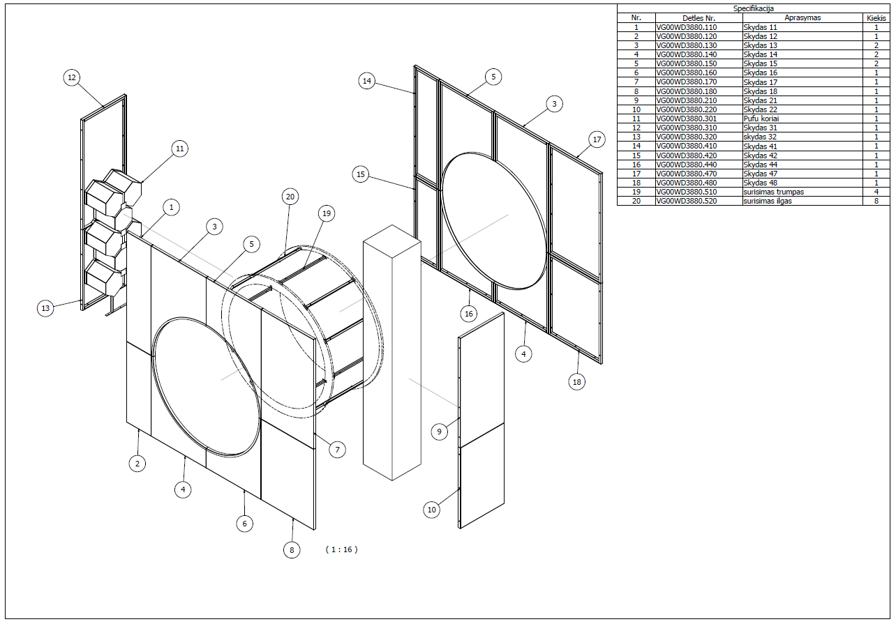
Nearly four sheets per module is a lot, and a client is entitled to ask why. The answer is that most of those modules are documented more than once — as fabricated steel, as folded metal, as panel work, and then again at the interfaces where those three meet.
Seventy-five sheets for twenty modules is what that coordination costs. It is meaningfully cheaper than discovering the clash during assembly, when the frame is welded, the metal is folded, and the only remaining option is to modify something on site in a retail unit that is trying to open.
There is also a load-path argument for documenting it properly. Children climb on this. The frame is what carries them, the fixings are what transfer it, and a drawing set that leaves either to the fabricator’s judgement is not a drawing set — it is a hope.
What the client received
- General arrangement and exploded view of the whole structure
- Steel frame assembly and welding drawings — tube lengths, joints, weld callouts
- Sheet metal bending schemes with bend lines, directions and angles
- Flat patterns for every folded part, ready for nesting
- Part drawings for the joinery carcassing
- Interface details where steel, metal and panel meet
- Cutting lists and material data per trade, as editable XLSX
What this project demonstrates
If your work is entirely panel furniture, the kitchen and the vanity unit are the more relevant examples.
This one matters if you take on retail, hospitality or fit-out work, where a piece is rarely just joinery. Bespoke retail furniture routinely combines steel, metal, glass, stone and panel, and the documentation problem is almost never the joinery — it is the coordination between trades that have never seen each other’s drawings.
That is the work I spent years doing on luxury retail fit-outs before going independent, and it is why I model in Inventor rather than in furniture-only software. More about that background.
Got a multi-material piece to document?
Send me the design intent — a PDF, a DWG, a survey, even a sketch — and you will get a price, a timescale and a recommendation on documentation depth within one working day. If you would rather see the quality of the drawings first, two complete sample packs are free to download.
Other projects
Client name, address and order number are withheld. Every drawing shown is published with permission.